Examples video
winLIFE is delivered with examples including all data for calculations so that the user can become familiar with the program. The data of some examples can be found in sub-directories named accordingly. The videos have been created over the previous few years and may differ slightly due to the improvements made in winLIFE.

Example 1 introduces you to the basics of the program with the help of examples for nominal stress concept.

In this example a square notched plate with a thickness of 5mm is calculated according to the nominal stress method.

In this example a square notched plate with a thickness of 5mm is calculated according to the local strain approach.

In this example, we compare the construction of a stress-strain path using only the material memory with the construction of a stress-strain path based on the rainflow procedure. For this purpose, an example is taken from literature and re-calculated.

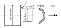
The component S-N curve is to be defined for an offset shaft made of rolled steel which is subject to bending and torsion loadings. This is then compared to the KFM-guidelines.

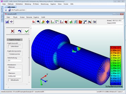
A time-varying torsion moment and pull-push forces are working on a cylinder. The course hast o be entered manually, the data transfer is explained and the results are analysed.

The example could be a realistic use from the engineering or vehicle manufacturing field. A steering system is subject to two individual groups of forces and the measurement values are available. The aim of the exercise of to calculate the fatigue life for the load collective obtained from the measurement.

A commercial vehicle wheel hub has been bound up with strain gauges and tested in the Europe test cycle. The static pre-load from the air pressure and the dynamic strain from the spring deflection are analysed separately and superposed as suitable. Various comparative stress hypotheses or damage parameters are examined and the test results compared.

You can start winLIFE with parameters using operating system commands – i.e. without GUI. In this way, running batch procedures can be defined automatically. This makes sense if you often have similar problems where you only have to change a few parameters. In this example we examine the influence of the endurance limit on the fatigue life. Starting with one project file, copies are made whereby only the parameter which varies – i.e the endurance limit – is changed. A batch file is created which runs several winLIFE calculations automatically.

A simple gear box is shown with a transmission of 1:10. It consists of only two gear wheels made of the same material. The dwelling period collective is made up of only a few steps. A simple fatigue life calculation for it is carried out.

In this example you can see how FEMAP (Version 9.3) works with winLIFE. A fatigue life calculation is carried out for a notched shaft which is loaded by a bending moment. To do this, unit load cases are defined in FEMAP and transferred to winLIFE. The results of the fatigue life calculation are then transferred back to FEMAP and shown there.

In this example we see how FEMAP (Version 9.3) works with winLIFE. For a complex component, a rear axle, the weld seams are calculated according to the r1-concept.
All the modelling and the use of sub-structures are shown here. The loading occurs with three measured load-time-functions. Three unit load cases in the direction of the wheel force are calculated in FEMAP and transferred to winLIFE. The results of the fatigue life calculation are then transferred back to FEMAP and shown there.

In this example a welded joint is modelled by plate elements using FEMAP. To meet the standards for fatigue calculation of welds according to the hot spot concept the mesh has to be created in a special way. The lines where the nodes are located are parallel and in a definite distance to the weld toe. The stress tensor needed for weld calculation is automatically created by stress tensor extrapolation.

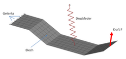
A simple model for a bridge where a load (representing a car) moves from one side to the other. This example demontrates the procedure by solving nonlinear problems. All model data are shipped that the user can follow this example hinself.

Aim is to demonstrate the collaboration of ANSYS and winLIFE and the use of the ANSYS macros. All data of the model are shipped that the user can follow this example hinself.

The use of the Endurance Limit Certification is shown in this example. It is a good introduction to the procedure. ![]()

Different procedures are analysed and compared with the theoretical results. ![]()
Showing how containerprojects can simplify the calculation of a great number of projects, which differ only in the loading. ![]()

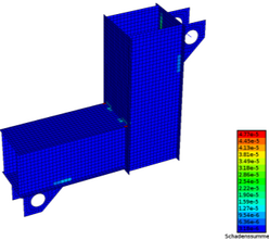
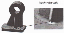
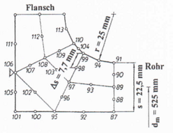
A seam weld is calculated according to the structural stress concept. Real loadings from measurements are used. ![]()

The hot spot search method is suitable for very large components with many weld seams. In this video the method is compared with the structural stress concept. Both methods are used with and without viewer.![]()

To take the rotation into account 4 unit load for one rotation are defined. This procedure is recommended in the case of rotating loadings. ![]()
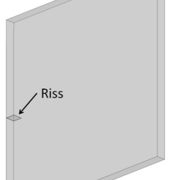
For a plate with an intial crack the crack growth is calculated using the Paris and Erdogan-Ratwani.![]()
The winLIFE embedded viewer is presented. It simplifies the result presentation inside winLIFE. ![]()
New nonlinear capabilities are included since version 3.7.2 and are demonstrated in this example.
A welded construction where test results of dynamic tests are available is calculated. The results of calculation are compared to the experiment results.
Example 6.1 of the FKM guideline is recalculated with local stresses. The static proof and the fatigue strength proof are calculated.
Example 6.2 of the FKM guideline, cast component, is recalculated with local stresses. The static proof and the fatigue strength proof are calculated.
Example 6.3 of the FKM guideline, compressor flange, is recalculated with local stresses. The static proof and the fatigue strength proof are calculated.